YAYLAGUL SK., 8/4 A. AYRANCI
06540 ANKARA TURKIYE
Tel:+90 312 468 8114
Faks:+90 312 468 8115
06540 ANKARA TURKIYE
Tel:+90 312 468 8114
Faks:+90 312 468 8115

Whether a medical product is assembled using mechanical fasteners, adhesives, ultrasonic welding, laser bonding, or resistance welding, it is critical that the finished product perform as designed. Product recalls caused by bond failures are, at best, expensive in terms of damage to the manufacturer's reputation and bottom line. At their worst, medical product bond failures can cause patient injury and invite product liability lawsuits, which can be economically ruinous.
For any product to perform as designed, it must be manufactured in a consistent manner and tested to ensure that specifications are being met. In other words, the requirements of the good manufacturing practice regulations (GMPs) must be met. This article focuses on how to establish an effective GMP program for the resistance welding bonding process and thus build in quality assurance.
BACKGROUND
Resistance welding uses a precisely controlled electrical current to melt defined areas on two metallic parts and then bond them together. Medical products suitable for the technique include, but are not limited to, battery packs, catheters, cauterizing wires, electrical terminals and connectors, heater elements, hybrid circuit connections, lamps, pacemakers, and sensors for pressure, temperature, and ultrasound. As the wide range in these products' sizes suggests, resistance welding can offer many manufacturers a reliable and low-cost alternative to soldering and mechanical fastening however, it is essential that appropriate GMPs are in place to ensure consistent weld quality.
If operators complain that a power supply is delivering weld power erratically, a manufacturer can be 100% certain that its procedures to control and verify the resistance welding process are inadequate. Creating an effective GMP program for the resistance welding process is essentially a three-step procedure: the manufacturer must define weld quality using a weld schedule profile, document the weld schedule, and verify GMP compliance.
WELD QUALITY AND THE WELD SCHEDULE PROFILE
Before GMP-compliant procedures can be developed for a specific resistance welding application, the company's marketing, engineering, and manufacturing departments must agree on a definition of weld quality. Marketing personnel are usually concerned about such visible indications of welding as burn marks or rough surfaces at the electrode contact point, while design engineers typically focus on quantitative measures, such as tensile or shear strength, and the manufacturing department views weld quality in terms of process consistency and ease of inspection.
It is not unusual for the three different focuses to create conflict. For example, marketing may insist there be absolutely no burn marks or surface deformation on the product, although engineering has set specifications for a very high tensile (or pull) strength and manufacturing does not want to polish the parts after welding. A conflict arises immediately because high-tensile-strength welds require the application of substantial weld force and heat, which will mar the part surface, thus forcing the use of a secondary polishing operation.
A road map to optimizing the resistance welding process and establishing process control, the weld schedule profile also offers a quantitative method for resolving such a quality definition conflict. The sample profile in Figure 1 graphs what happens to pull strength when weld heat is varied systematically while weld force is kept constant. Other measures of weld quality such as shear strength, depth of the weld mark, and electrode displacement can be plotted against changes in weld heat in a similar fashion. The following analysis of the data in the figure shows how compromise can be achieved in the conflict described above.
Using an 8-lb electrode force (represented by Curve A) would provide a maximum pull strength of approximately 11.0 lb, over a very narrow weld-heat range of 50 to 58 Ws. Those results would not satisfy engineering, which wants a greater pull strength, or manufacturing, which wants a wider heat range. Curve C would provide the greatest pull strength at 13.5 lb; however, manufacturing would again have to sacrifice process consistency because the weld-heat range is also quite narrow. Using a 14-lb force (Curve D) would be to tally unsatisfactory. Marketing would not accept the large marks created by the high weld force, while the low pull strength and tight weld-heat range are cause for rejection by engineering and manufacturing.
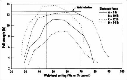
Therefore, the optimum weld force is that represented by Curve B. Its relatively flat peak indicates that weld heat can vary from 45 to 70 Ws, producing a maximum variation in pull strength ranging from 12.0 to 12.5 lb, a total change of 0.5 lb. This small variation in product pull strength over such a large change in weld heat is great news for manufacturing because it offers the consistency that is a key part of their weld quality definition. Engineering can accept the pull strength as sufficient since the product will see a maximum pull force of only 4 to 5 lb in the field. Marketing is also satisfied because the mark produced by a 10 lb weld force is significantly less than those made by welding at 12 or 14 lb. In short, by examining the weld schedule profile, all parties can quickly reach agreement on the weld quality definition.
To create a weld schedule profile such as the one in Figure 1, the process engineer be gins a series of tests by setting the weld force to an arbitrarily low value. Holding the weld force constant, he or she adjusts the heat from the welding power supply to create a bond that barely holds together. Five to ten welds are then made at that setting, and the resulting tensile or shear strength, electrode displacement, dynamic weld force, weld current, and weld voltage are recorded be fore the weld heat is increased and the entire measurement procedure is repeated. (All of these measurement parameters will be used for weld quality correlation analysis, which is described later in this article.) Each group of welds is averaged to create a single data point. When the electrodes begin to stick to the parts or heavy expulsion of part material begins to occur during the welds, the process engineer should terminate testing at this weld force and repeat the entire process at a higher force.
WELD SCHEDULE DOCUMENTATION
The GMP regulations mandate that all procedures be documented adequately and updated and verified periodically. The GMP documentation package for a single resistance welding operation should include the weld schedule profile procedure and the weld schedule profile, part fabrication data and drawings, power supply settings, weld- force settings, electrode and weld-fixture fabrication drawings, personnel training procedures, and a procedure for verifying weld quality. The weld schedule profile was de scribed above; the other areas of concern will be discussed in the remainder of this article.
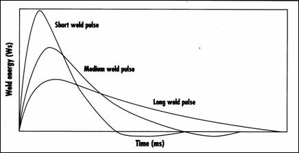
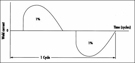
Figure 3.
Typical output waveform of a direct-energy power supply.
Part Fabrication Control. All fabricated parts must be manufactured according to a controlled source document that defines the part as to its alloy, dimensions, and plating (if any). No changes can be made to these parameters without generating a new weld schedule profile. Even minor modifications in the part alloy, thickness, plating type, or plating thickness, which may re duce costs or seem to improve the product design, can radically alter the welding process, causing sparking or over- or under- heating of the parts. Plating control is of particular importance. For example, increasing the nickel plating thickness on a steel part from 0.0005 in. (0.0125 mm) to 0.001 in. (0.025 mm) will cause a substantial reduction in pull or shear strength.
Power Supply Control. Figure 2 shows a series of output weld pulses for a stored- energy (capacitive discharge) power supply, which is the type commonly used for welding small medical products such as catheters, cauterizing wires, hybrid circuit connections, pacemakers, and sensors. For a particular welding operation, weld heat is set by changing the energy level that is stored in the capacitor bank, and weld time is set by selecting the pulse width, as measured in milliseconds, that best matches the thermal response of the parts being welded. For ex ample, a short weld pulse is best for welding brass and copper parts, while medium and long weld pulses are needed to weld thermally slow materials such as nickel and stainless steel.
Figure 3 shows one cycle of output weld pulses for a direct-energy (alternating cur rent) power supply. In these systems, weld heat is set by varying the percentage of total weld current available from the power sup ply, and weld time is set by adjusting the number of power cycles during which weld current flows. Direct-energy supplies should be used for welding large battery pack assemblies, electrical connections, and heater elements.
Weld-Force Control. Consistent resistance welding requires the use of a force-fired weld head with low inertial follow-up. Inertial follow-up is the ability of the weld head to hold the welding electrodes firmly against the parts as they become plastic and melt in melting periods as short as 2 milliseconds. Heavy part-material expulsion is symptomatic of poor inertial follow-up capabilities. Forced-fired weld heads have two design features that contribute to resistance welding consistency: firing signals are sent to the welding power supply only when the user-set weld force is reached, and weld force is independent of part thickness.
Static weld force is typically measured by placing a U-shaped force gage between the welding electrodes and then recording the weld force necessary to fire the power supply. Dynamic weld force can be measured by attaching a low-mass accelerometer or strain gage to the moving electrode holder as close to the actual welding electrode as possible.
Electrode and Weld-Fixture Fabrication Control. Because the parameters measured in a weld schedule profile are very sensitive to changes in the electrode alloy and dimensions, a controlled fabrication drawing must be created for each electrode used in the resistance welding process. Only those alloys under Resistance Welding Manufacturers Association control should be used; free-machining copper is not acceptable and causes welding inconsistencies. Tight manufacturing control of electrode tip diameter and length are also critical to the resistance welding process. Operators or machine technicians must not be allowed to dress electrode tips using a file or any other tool that will negatively affect the quality of the electrode tip surface or the alignment of the electrode tip face to the part surface.
Controlled fabrication drawings for welding fixtures are another integral part of the GMP documentation package. Changes in a weld-fixture alloy or dimensions will affect how weld heat is built up in or drawn out of the parts during the welding process, which in turn alters the weld schedule profile.
Personnel Training. Machine technicians and operators must be taught how to install welding electrodes properly, how and when to clean electrode tip faces, and how to position electrode tips on the parts to be welded. Electrode tip faces that are not parallel to the parts will cause random part-material expulsion, and it is imperative that 100% of each electrode tip face is in contact with the part. Diagrams showing proper electrode installation and electrode positioning on the parts are excellent teaching aids as well as process control documents.
Although operators and machine technicians can be taught how to clean electrode tip faces properly, it has been found that those companies that do not permit any on line modifications or cleaning of electrode tip faces experience very few welding problems caused by electrode maintenance. Typically, such companies remove the electrodes on a scheduled basis for controlled resurfacing in the tool crib according to instructions listed on the electrode fabrication drawing.
VERIFYING GMP COMPLIANCE
Periodic random audits of the weld schedule profile only provide snapshots that capture the process at a single point in time. Real-time, nondestructive, continuous monitoring of the resistance welding process is the only way to detect negative process trends and individual problem welds. For Class III medical products subject to the GMP regulations, continuous monitoring of the resistance welding process also provides the needed hard data that product assembly specifications are being met.
Clearly, performing a destructive pull test on each part as it comes off the production line is infeasible, because no products would remain to ship out the door. However, if a nondestructive indication of weld quality can be correlated to pull strength, then only a limited number of parts need be sacrificed for testing. Such indicators of weld quality include weld temperature, weld acoustics, electrode displacement, dynamic weld force, weld current, and weld voltage.
Measuring weld temperature is difficult for two reasons. First, the electro-optical response time of infrared sensors is usually longer than the weld period, and, second, on the factory floor sensor eyes quickly become occluded with dirt and part materials. Measuring weld acoustics in a noisy factory environment is equally difficult, and the techniques used to measure electrode displacement and dynamic weld force also present difficulties. Low-mass sensors must be used so that the inertial follow-up capabilities of the weld head will not be affected, and they must be placed as close to the electrode as possible in order to obtain meaningful displacement or force data. In contrast, weld current and weld voltage measurements are relatively easy to make and data can be gathered on a real-time basis with a host computer. Therefore, the remainder of this article will focus on correlating pull strength with weld current and weld voltage.
Weld Quality Correlation. Determining the correlation between various weld quality data is not an easy task. The process engineer cannot simply make 5 to10 welds at several weld-heat settings, perform a pull strength test, and then expect to set process control limits. Correlating pull strength data with weld current or weld voltage requires making hundreds, perhaps thousands of welds under the controlled operating conditions specified by the weld profile schedule to establish correlation.
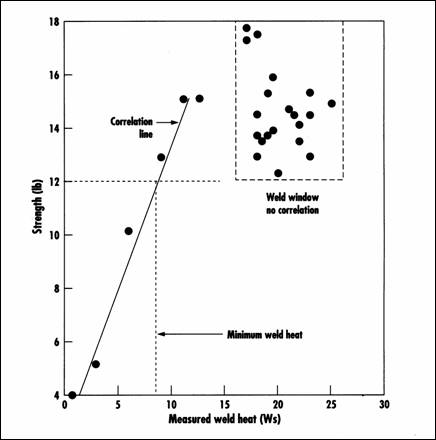
Figure 4 represents a weld correlation, diagram that shows how pull strength correlates with weld heat, as measured across the parts welded under Curve B operating conditions in Figure 1. At first glance, the weld correlation diagram is very similar to its sister weld schedule profile, but there are some key differences. First, the relationship between the set weld heat and the measured weld heat across the weld parts is not linear, because weld heat is lost in the welding cables as they heat up during production. Second, when the system is operating in the weld window, shown in Figure 1 as the flat segment of the curve, correlation disappears because pull strength is relatively independent of weld heat. However, the absence of correlation in the weld window does not render the weld correlation diagram useless; in fact, the diagram provides the assurance that as long as the measured weld heat ranges between 9 and 25 Ws, the minimum pull strength will always be greater than 12 lb. Since statistical process variations exist, the process engineer should set the lower limit of measured weld heat to a value greater than 9 Ws in order to accommodate the low end of the statistical range.
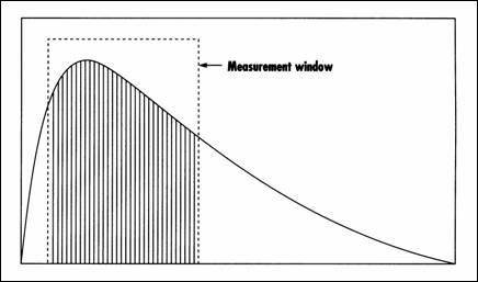
Weld Monitor Capabilities. By using microprocessor-based monitors to measure weld current and weld voltage the process engineer gains the ability to detect no-weld conditions, material thickness changes, pull test variations outside the weld window, electrode oxide buildup, and electrode position variation. In addition to accurately measuring both the weld-current and weld-voltage output waveforms, a monitor's ability to zero in on specific output waveform areas is important to producing weld quality data that can be correlated with pull or shear strength. For example, Figure 5 shows the weld-current output waveform for a stored-energy power supply. The measurement window was set to capture the mid region, which is considered to be the most significant portion of the waveform in terms of weld quality content.
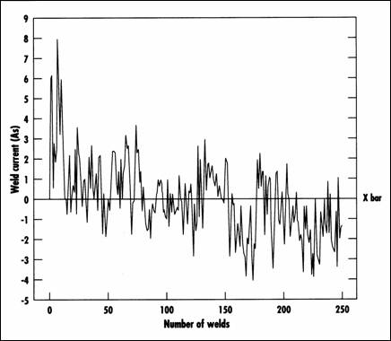
At a minimum, a weld monitor also should offer continuous or periodic RS-232 transmission of weld current and weld volt age for each weld so that this data can be output to a serial printer or collected on a personal computer. A built-in statistical process control software package that offers run charts, X bar and R bar control charts, and statistical summary information is also desirable. The X bar control chart in Figure 6 shows the effect of electrode oxide buildup on weld current for 250 welds; the measurement parameter is the integration of weld current over the user programmed weld-window time period. Note that the maximum peak-to-peak variance is fairly stable, indicating a well-controlled welding process. The shift in the measurement trend at 125 welds occurred after the electrodes were cleaned.
CONCLUSION
Establishing a GMP program for a resistance welding process is no longer an option for medical device manufacturers, but a requirement for obtaining marketing approval and passing periodic FDA facility inspections. While creating such procedures is not difficult, it must be done carefully and thoroughly. The extensive understanding of the welding process that is gained through that exercise will result-in improved product yields and increased profitability, and will successfully prevent weld joint failures in the field that lead to product recalls and a damaged company reputation.
| Home | Back to Index of Articles | Back to Previous Page |